Pico Relay Board
Raspberry Pi Pico Relay Board is developed by SB Components with the potential to control up to 4 appliances and loads up to 250V AC@ 7A, 30V DC@ 10A. It provides a way for the users to control the high voltage/current devices.
Features
4 High-quality Relay and loads up to 250V AC@ 7A, 30V DC@ 10A.
Optocoupler (CTR: 50~600% at IF =5mA, VCE =5V)
Indication LED’s for Relay output status.
Relay control jumpers allow the user to control the relays by custom pins other than the default pins.
40-Pin Stacking Header for Pico.
40 Pin External Male Headers for GPIO
Specifications
Channel - 4
Operating Voltage - 5V
Switching Voltage (VAC) - 7A/ 250V
Switching Voltage(VDC) - 10A/ 30V
Indication LED’s for Relay output status.
Dimensions - 58 x 21 mm
Pinout
Installation
MicroPython
Connect Raspberry Pi Pico on female header of Pico Relay Board.
Connect USB cable on Raspberry Pi Pico USB port.
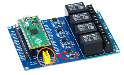
Make sure default jumpers are connected for each relay
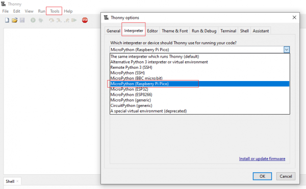
Choose interpreter as MicroPython (Raspberry Pi pico).
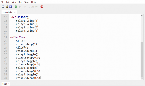
Now use example code "Test.py" from pico relay board's github repository in thonny ide.
Source code : https://github.com/sbcshop/Raspberry-Pi-Pico-Relay-Board
Copy and paste or open code in thonny ide.
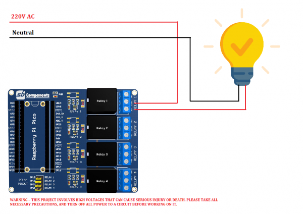
You can connect external devices such as Bulb, fan, appliances etc as shown in below circuit:
Click on green play button to run example of Pico Single channel Relay HAT.

Note: You can use any other GPIO of Raspberry Pi Pico by removing the default jumper and connecting it to GPIO using jumper cables.
Resources


