Difference between revisions of "LoRa-HAT-for-Raspberry-Pi"
From SB-Components Wiki
| Line 52: | Line 52: | ||
== Installation == | == Installation == | ||
| − | |||
| − | |||
| − | |||
| − | |||
| − | |||
| − | |||
| − | |||
| − | |||
| − | |||
| − | |||
| − | |||
| − | |||
| − | |||
| − | |||
| − | |||
| − | |||
| − | |||
| − | * In the folder you see | + | === '''For Communication between two LoRa Hat === |
| − | + | ||
| − | * | + | [[File:LORA1.jpg|400px]] |
| − | + | ||
| − | + | * First take 2 LORA Hat boards and set jumper position as mentioned below: | |
| − | + | * ''' Mode Selection Jumper:''' we are going to use pi GPIO pin 13 and 15 to control MODE Selection | |
| − | + | * '''LoRa mode selection jumpers''' | |
| − | + | * short M0, short M1: transmission mode (In this project we use transmission mode) | |
| + | * short M0, open M1: configuration mode (You can configure the Lora via this mode) | ||
| + | * open M0, short M1: WOR mode | ||
| + | * open M0, open M1: deep sleep mode | ||
| + | |||
| + | * '''Device Selection Jumper(Board Selection, This is also mention in the board) :''' | ||
| + | * Set it as '''MODE 1''' to enable USB to LORA Communication (Without raspberry pi) | ||
| + | * Set it as '''MODE 2''' to enable PI to LORA Communication (With raspberry pi) | ||
| + | |||
| + | |||
| + | === Code === | ||
| + | In this folder you see two python codes | ||
| + | * Lora_transmitter.py -> run this file to transmit the data (any data eg: sensor data,any string and message etc) | ||
| + | * Lora_receiver.py -> run this file to receive data from other lora | ||
| + | |||
| + | === '''Applications''' === | ||
| + | In this folder you see two application | ||
| + | * Pi Lora Broadcast (with LCD display), In this folder you see three files | ||
| + | * PCLinuxOSFonts -> this folder contains various fonts | ||
| + | * transmitter.py -> run this file to broadcast the data (any data eg: sensor data,any string and message etc) | ||
| + | * receiver.py -> run this file to receive broadcast data from other lora | ||
| + | * ST7789.py -> this is the lcd library file | ||
| + | |||
| + | * Pi Lora Homeautomation (with LCD display), In this folder you see three files | ||
| + | * pi_lora_transmitter_home_automation.py | ||
| + | * pi_lora_receiver_home_automation.py | ||
| + | * ST7789.py | ||
| + | |||
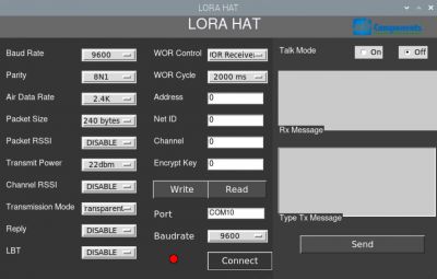
| + | === '''Lora GUI (run with the help of GUI)''' === | ||
| + | For this, you need to use Lora onboard USB (use jumper wire at board selection 1) | ||
| + | Go to the Lora GUI folder, and run the LORA_GUI.py file. from this file, you can configure the Lora and you are able to transmit, receive the data (eg: baud rate, channel, etc) | ||
| + | |||
| + | [[File:LORA2.jpg|400px]] | ||
== Resources == | == Resources == | ||
<b> Github </b> | <b> Github </b> | ||
* [https://github.com/sbcshop/Pico-Barcode-HAT.git Source Code] | * [https://github.com/sbcshop/Pico-Barcode-HAT.git Source Code] | ||
Revision as of 11:52, 21 January 2022
LoRa HAT for Raspberry Pi (433/868/915)
LoRa™ HAT, a low-power consumption data transmission module, comes with an onboard CH340 USB TO UART converter, Voltage Level Translator(74HC125V), E22-900T22S and E22-400T22S SMA antenna connector, IPEX antenna connector, LoRa™ Spread Spectrum Modulation technology with auto multi-level repeating.
Features
- Communication range up to 5 KM
- Supports auto repeating to transmit longer
- Low Power Consumption
- Highly Secured
- For Evaluating signal quality with the RSSI or “Received Signal Strength Indicator”
- Wireless parameter configuration support
- Fixed-point transmission support
- SMA and IPEX Antenna Connector
- USB to LORaTM and Pi to LoRaTM Communication via UART
- Comes with development resources and manual
- LED Indicators:
RXD/IXD: UART RX/TX indicator
AUX: Auxiliary indicator
PWR: Power indicator
- Serial/USB selection Jumpers:
A: USB TO DART to control the LoRa module through USB
B: Control the LoRa module through Raspberry Pi
- Data/Command made selection jumpers:
Short M0, short M1: Transmission mode
Short M0, open M1: Configuration mode
Open M0, short M1: WOR mode
Open M0, open M1: Deep sleep mode
Specifications
- Frequency - 915/868/433 MHz
- Power - 22dBm
- Distance - Up to 5 KM
- Interlace - DART Communication
- Serial Port Module - E22-900T22S/E22-400T22S
- Voltage Level Translator - 74HC125V

Installation
For Communication between two LoRa Hat

- First take 2 LORA Hat boards and set jumper position as mentioned below:
 *  Mode Selection Jumper: we are going to use pi GPIO pin 13 and 15 to control MODE Selection
  * LoRa mode selection jumpers
    * short M0, short M1: transmission mode (In this project we use transmission mode)
    * short M0, open M1: configuration mode (You can configure the Lora via this mode)
    * open M0, short M1: WOR mode
    * open M0, open M1: deep sleep mode

 * Device Selection Jumper(Board Selection, This is also mention in the board) :
   * Set it as MODE 1 to enable USB to LORA Communication (Without raspberry pi)
   * Set it as MODE 2 to enable PI to LORA Communication (With raspberry pi)
Code
In this folder you see two python codes
  * Lora_transmitter.py -> run this file to transmit the data (any data eg: sensor data,any string and message etc)
  * Lora_receiver.py    -> run this file to receive data from other lora
Applications
In this folder you see two application
  * Pi Lora Broadcast (with LCD display), In this folder you see three files
      * PCLinuxOSFonts -> this folder contains various fonts
      * transmitter.py -> run this file to broadcast the data (any data eg: sensor data,any string and message etc)
      * receiver.py    -> run this file to receive broadcast data from other lora
      * ST7789.py      -> this is the lcd library file

  * Pi Lora Homeautomation (with LCD display), In this folder you see three files
      * pi_lora_transmitter_home_automation.py
      * pi_lora_receiver_home_automation.py
      * ST7789.py
Lora GUI (run with the help of GUI)
For this, you need to use Lora onboard USB (use jumper wire at board selection 1) Go to the Lora GUI folder, and run the LORA_GUI.py file. from this file, you can configure the Lora and you are able to transmit, receive the data (eg: baud rate, channel, etc)

Resources
Github