Difference between revisions of "Motor-Driver-Microbit"
From SB-Components Wiki
| Line 56: | Line 56: | ||
https://cdn.shopify.com/s/files/1/1217/2104/files/add_ext1.png | https://cdn.shopify.com/s/files/1/1217/2104/files/add_ext1.png | ||
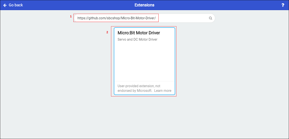
| − | <li> Click on | + | <li> Click on Search button after entering above url, Now look for the search result to add the extension to the project(current). makecode micro:bit </li> |
| − | + | https://cdn.shopify.com/s/files/1/1217/2104/files/add_ext2_1.png?v=1608196970 | |
| + | |||
<li> Control your servo motor and DC motor by motor driver Extension drag and drop blocks as shown in below example. | <li> Control your servo motor and DC motor by motor driver Extension drag and drop blocks as shown in below example. | ||
== Resources == | == Resources == | ||
Revision as of 05:40, 12 May 2021
Motor Driver for Micro:Bit
Motor Driver for micro:bit is introduced as the latest edition of a range of SB Components that can interface with up to 2 DC motors and 3 pwm based Servo motors. It works on Motor Power supply: 6V~12V (VIN terminal) an output current of up to 3A with a powerful integrated TB6612FNG Module IC that scales up the performance. VIN terminal can be used for providing the power to the Motor driver for micro:bit.
Features
Specifications

Pinout
| PIN | Description |
|---|---|
| Vcc | Power (6~12V) |
| GND | Ground |
| MA1 | Positive Terminal of motor A |
| MA2 | Negative Terminal of motor A |
| MB1 | Positive Terminal of motor B |
| MB2 | Negative Terminal of motor B |
| P0 | Servo 1 Control Pin |
| P1 | Servo 2 Control Pin |
| P2 | Servo 3 Control Pin |
Programming
Drag and Drop
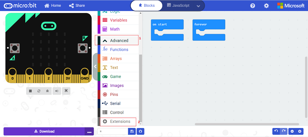
Many people want to learn the process to learn more about micro:bit by getting an understanding of the potential of micro:bit. If one wants to run servo motor and C motor with the micro:bit motor driver then they can do the following steps.
https://github.com/sbcshop/Micro-Bit-Motor-Driver
https://cdn.shopify.com/s/files/1/1217/2104/files/add_ext2_1.png?v=1608196970